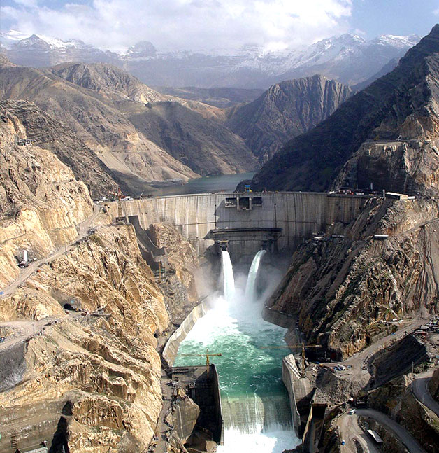
Karun III Dam & Hydropower Plant Project

Project Purpose / Layout

To utilize hydroelectric energy of the Karun River in the location of Karun III dam by building a 205-m high concrete double curvature arch dam, 2000-MW underground powerhouse comprising of eight 250-MW units generating 4172x106 KWH per annum and by controlling floods and annually regulating about 1x10⁹ m3 water for irrigation consumption.

Geographic Location
The Karun III powerhouse is situated 28-km to the east of the town of Izeh in the northeast of Khuzistan province in Iran. The dam site lies 610 km to the estuary of the Karun River and its aerial distance from the city of Ahvaz is in the vicinity of 140 km. The major tributaries of the Karun River rise in the Zard Kuh Mountain of the Bakhtiari district in the Zagros Range.

Project History
- The phase I studies were begun by Water & Land Development Company and Acres International Company (Canada) in 1978 and continued until 1989. Accordingly, the complementary studies as well as phase II detailed design studies were assigned to 'Mahab Ghodss – Acres' Joint Venture to be carried out by 1993.
- The minor construction items including access road, bridges and temporary camp started in 1991 and finished in 1994. Construction of the dam and power plant began in 1994 and ended in 2004.

Specific Characteristics of Project
- The largest water reservoir among the concrete double curvature arch dams in Iran.
- The largest powerhouse cavern in Iran as well as one of the 10 large powerhouse caverns in the world.
- The largest arch bridge in Iran.

Technical Specifications of Project
|
Dam |
|
|
Dam type |
Concrete double curvature arch dam |
|
Dam height above foundation (m) |
205 |
|
Dam crest length (m) |
462 |
|
Dam crest width (m) |
5.5 |
|
Dam body volume (m3) |
1000 x 103 |
|
Total reservoir volume (m3) |
3000 x 106 |
|
Active reservoir volume (m3) |
1750 x 106 |
|
Mean annual inflow (m3/s) |
300 |
|
Spillways |
|
|
A) Ogee spillway (chute spillway) on the right abutment of the dam which consists of two bays, each is equipped with a radial gate and a series of stoplogs. |
Discharge capacity: 8710 m3/s |
|
B) Two orifice spillways in the middle of the dam which are equipped with two radial service gates and two emergency gates. |
Discharge capacity: 2885 m3/s |
|
C) Free spillway (crest spillway) in the middle of the dam crest which consists of three bays without gate. |
Discharge capacity: 1800 m3/s |
|
Total spillways discharge capacity |
13395 m3/s |
|
Powerhouse |
|
|
Powerhouse type |
Underground |
|
Number of units |
8 |
|
Design head (m) |
161 |
|
Installation capacity (MW) |
2000 |
|
Mean annual generation (GWH) |
4172 |
|
Diversion System |
|
|
Number of diversion tunnels |
2 |
|
Length of diversion tunnel # 1 (right bank) |
613 m |
|
Final diameter of diversion tunnel # 1 |
13 m |
|
Cross section of diversion tunnel # 1 |
Circular |
|
Discharge capacity of diversion tunnel # 1 |
1800 m3/s |
|
Length of diversion tunnel # 2 (left bank) |
536 m |
|
Final diameter of diversion tunnel # 2 |
13 m |
|
Cross section of diversion tunnel # 2 |
Horseshoe |
|
Discharge capacity of diversion tunnel # 2 |
1500 m3/s |
|
Power Plant Tunnels & Shafts |
|
|
A) Power intake tunnels |
3 Tunnels (Tunnel # 3 is considered for development of powerhouse in the future) |
|
Final diameter of power intake tunnels |
12.6 m |
|
Length of power intake tunnel # 1 |
67 m |
|
Length of power intake tunnel # 2 |
136 m |
|
Length of power intake tunnel # 3 |
175 m |
|
B) Upper power tunnels |
4 Tunnels |
|
Final diameter of upper power tunnels |
9.5 m |
|
Length of upper power tunnel # 1 |
134 m |
|
Length of upper power tunnel # 2 |
154 m |
|
Length of upper power tunnel # 3 |
122 m |
|
Length of upper power tunnel # 4 |
144 m |
|
C) Power shafts |
4 Shafts |
|
Diameter of power shafts |
9.5 m |
|
Height of power shafts |
116.40 m |
|
D) Lower power tunnels |
4 Tunnels (Each tunnel is divided into 2 penstocks each of which is 67.5 m in length and 5.5 m in diameter) |
|
Final diameter of lower power tunnels |
9.5 m |
|
Length of upper power tunnel # 1 |
134 m |
|
Length of upper power tunnel # 2 |
154 m |
|
Length of upper power tunnel # 3 |
122 m |
|
Length of upper power tunnel # 4 |
144 m |
|
Total length of tunnels, galleries and caverns |
18940 m |
|
Total length of shafts |
1664 m |
|
Number of shafts |
27 (4 intake shafts, 4 power shafts, surge shaft, bus shaft, access shaft to grouting galleries and elevator shaft) |
|
Flow Compensation Outlet System |
|
|
Number of outlets |
2 Outlets in the middle of the dam body (each outlet is 32 m in length and equipped with a discharge valve) |
|
Diameter of flow compensation outlet system |
2.2 m |
|
Discharge capacity of flow compensation outlet system |
250 m3/s |
|
Access Roads |
|
|
Total length of access roads |
9 km |


